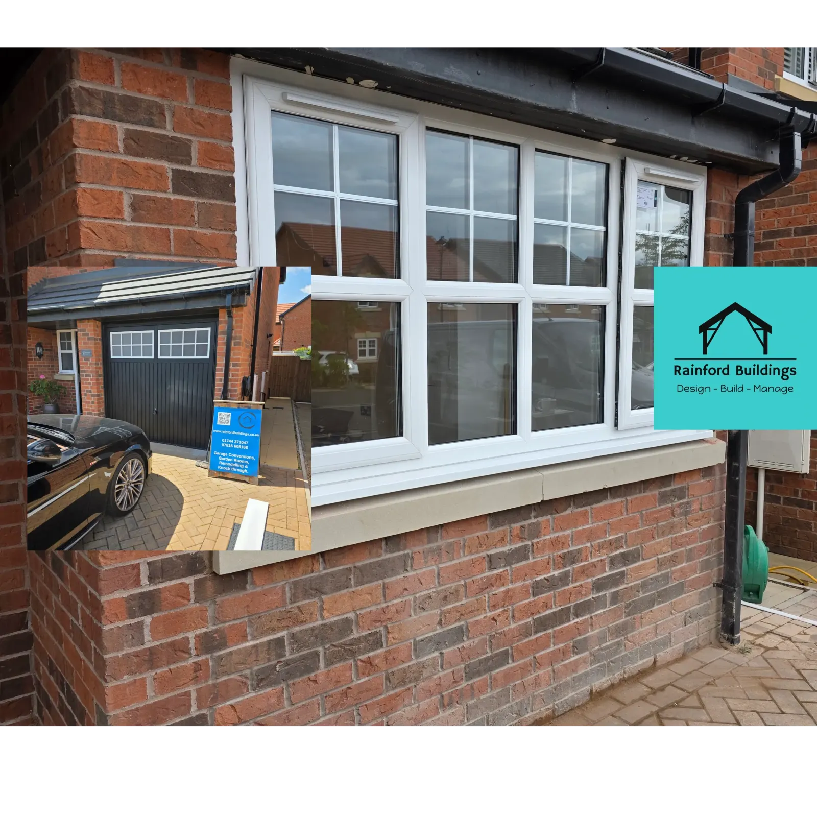
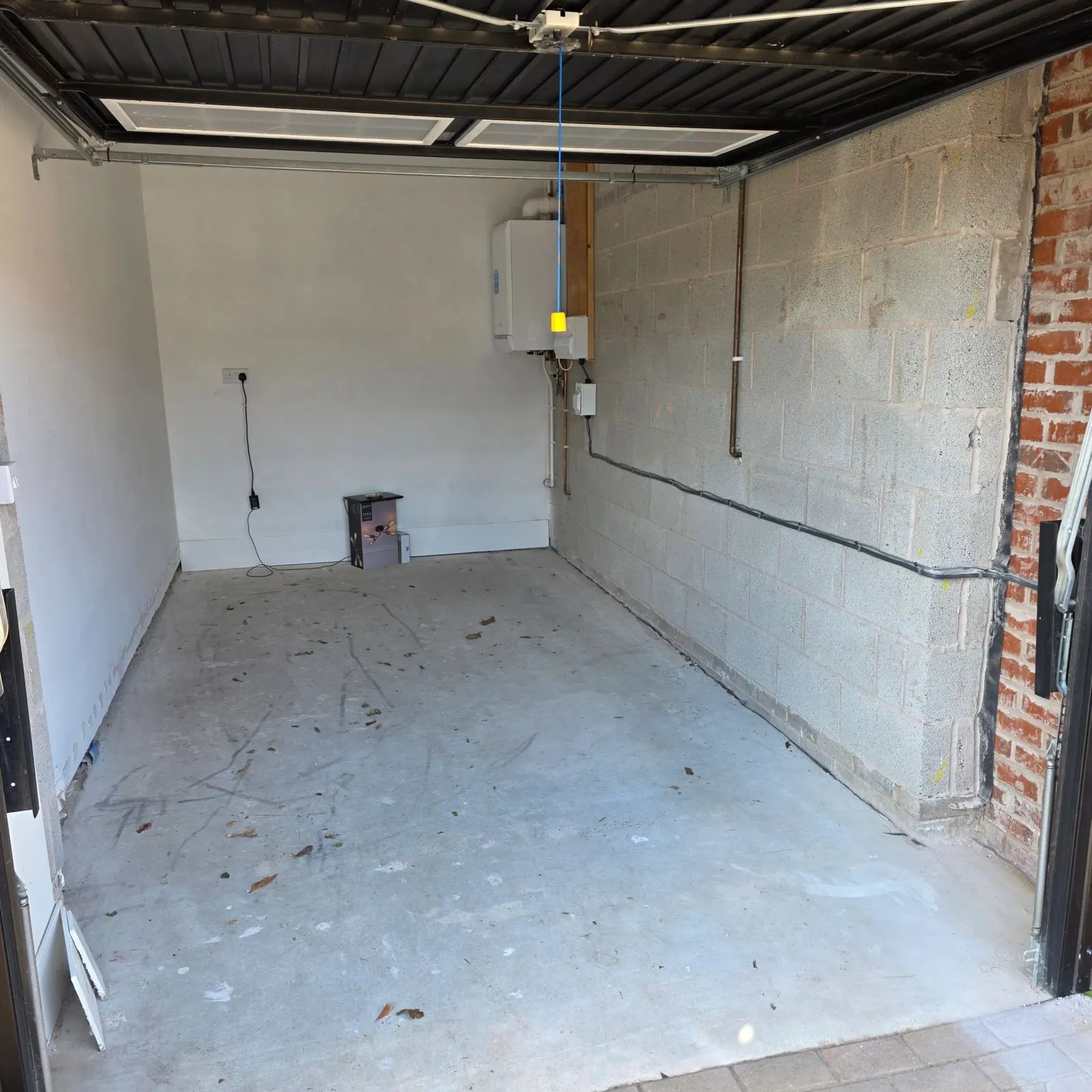
what does a Hip Roof look like
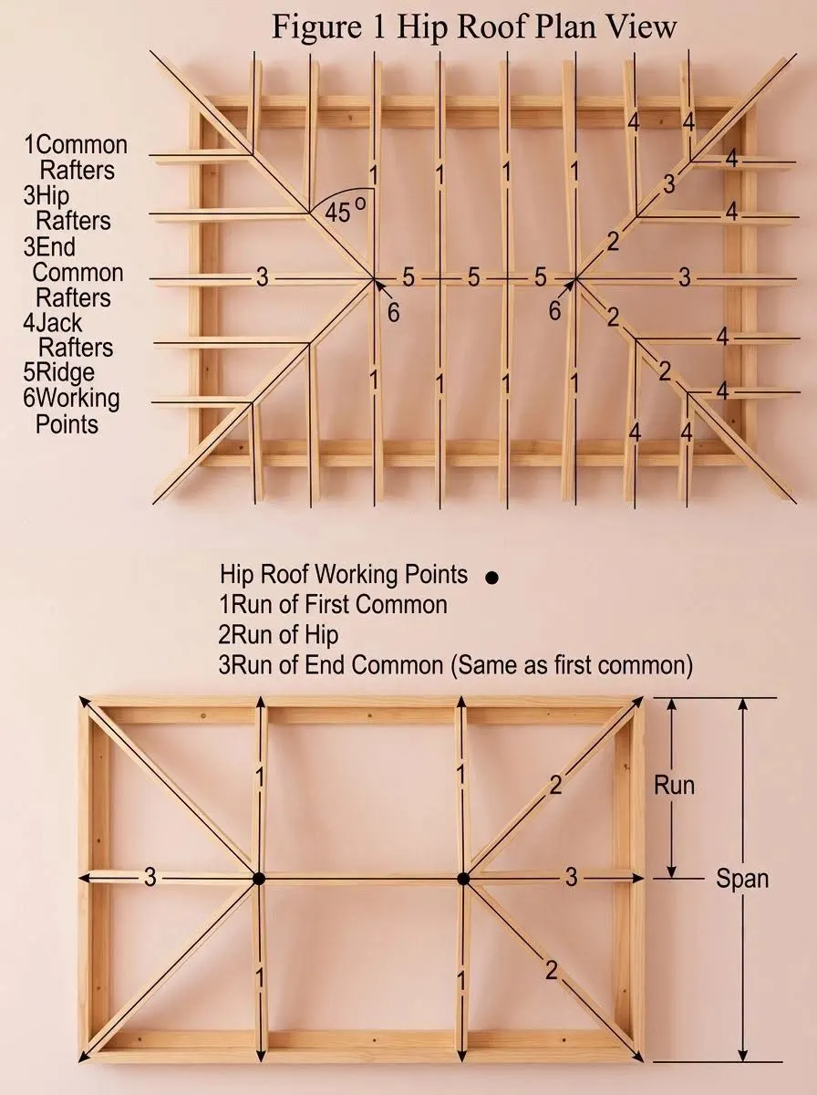
Hip Roof Framing and Geometry Plan View
This image illustrates the structural framing plan and geometric layout of a standard hip roof system, showcasing how various rafters intersect to form a self-supporting sloped roof. It highlights the spatial relationships, mathematical runs, and working points necessary for carpenters and engineers to calculate precise rafter lengths and pitches. Understanding this layout is essential in construction to ensure the structural integrity and proper load distribution of a building’s roof.
System Components
Common Rafters (1): Standard rafters that extend vertically from the top wall plate to the center ridge board, establishing the main slope of the roof.
Hip Rafters (2 & 3): Diagonal rafters that form the intersection of two adjacent sloped roof surfaces, meeting at a 45-degree angle in plan view.
End Common Rafters (3): Rafters located at the ends of the structure that extend from the end wall plate horizontally to the working points of the ridge.
Jack Rafters (4): Shorter rafters that bridge the gap between the wall plates and the diagonal hip rafters.
Ridge (5): The central horizontal framing member at the peak of the roof where the main common rafters and hip rafters connect.
Working Points (6): Critical geometric intersection points where the centerlines of the ridge, common rafters, and hip rafters meet for accurate measurement layout.
Span and Run: Key dimensional measurements where the span represents the total width of the frame, and the run equals exactly half the span, defining the horizontal distance a common rafter covers.
Overall Interpretation
The diagram serves as a clear technical guide for visualizing how individual lumber components fit together to form a complex three-dimensional hip roof from a top-down perspective. By defining the exact relationships between the run of the common rafters and the diagonal path of the hip rafters, it demonstrates the geometric principles used to calculate precise rafter cuts. Ultimately, the illustration emphasizes that careful alignment at designated working points is crucial for achieving a balanced and structurally sound roof frame.